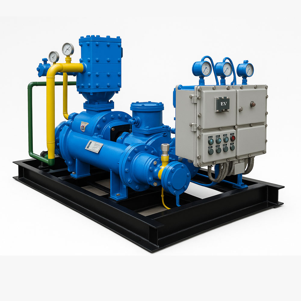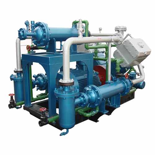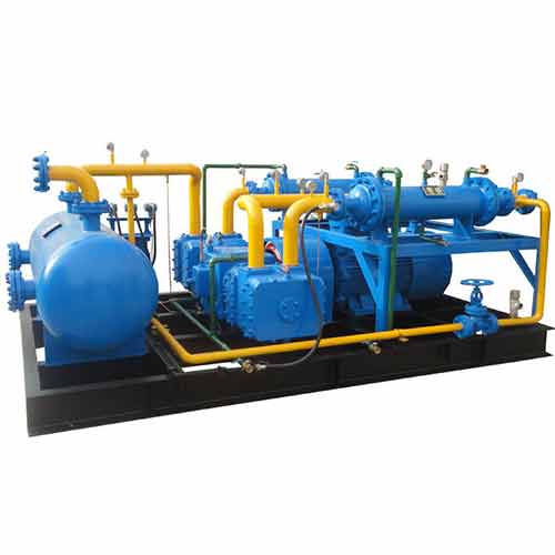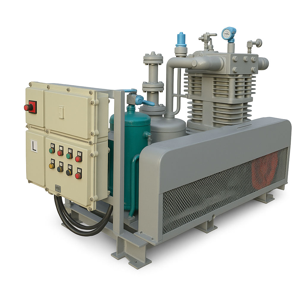
Industry Compressor For Oil Field
Industry Compressor For Oil Field
- Application: Industry Gas
- Place of Origin: China·Xuzhou
- Compressor structure: Piston Compressor
- Volume flow: 3NM3/hour~1000NM3/hour (customized)
- Voltage: 380V/50Hz (customized)
- Maximum outlet pressure: 100MPa (customized)
Description
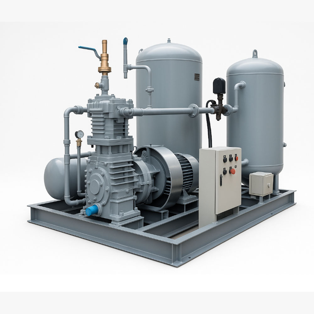
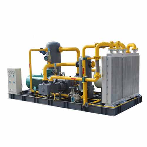
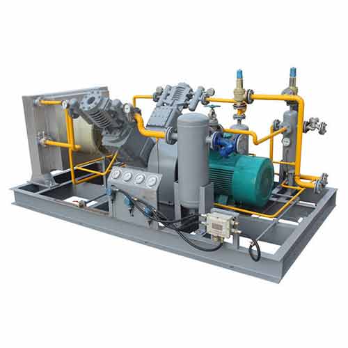
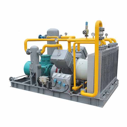
An Industry compressor for oil fields is a pivotal component in hydrocarbon extraction, processing, and transportation. This specialized equipment serves the crucial function of increasing the pressure of gases, primarily natural gas, to facilitate their efficient movement through pipelines. In the context of oil fields, compressors are instrumental in enhancing the productivity of wells through techniques like gas lift systems and enhanced oil recovery (EOR). They play a vital role in maintaining reservoir pressure ensuring a steady flow of oil and gas to the surface for further processing.
Features & Characteristics:
- Capacity and Flow Rate: IndustryCompressors for oil fields should be able to handle the required volume of gas and provide a high flow rate to meet the demands of the extraction process.
- Pressure Ratio: A compressor’s ability to increase gas pressure efficiently is crucial. It should be capable of achieving the required pressure ratios to facilitate proper transportation.
- Scalability: Compressors are often scalable to accommodate changes in production volumes. It provides the flexibility needed to adapt to fluctuations in oil field output.
- Modular Configurations: Modular designs allow for easier installation, maintenance, and upgrades. It also enables operators to adapt the compressor system to changing operational requirements.
- Remote Monitoring and Control: Compressors should have advanced communication systems to facilitate real-time monitoring and control. This allows operators to manage operations efficiently and address issues promptly.
Main Structure: Compressor for oil field
- The structure includes a robust compressor housing that encases the compression mechanism, providing a protective environment for efficient operation.
- Compressors for oil fields are equipped with a power transmission system that drives the compression process.
- These components regulate gas flow, controlling the intake and release of hydrocarbons to maintain optimal pressure levels during the extraction and transportation.
- Sophisticated control systems are integrated into the compressor structure, monitoring and adjusting operational parameters for optimal performance, efficiency, and safety.
- The structure is engineered with durability in mind, designed to withstand the challenging environmental conditions prevalent in oil fields.
- Given the harsh conditions of oil fields, the compressor structure is designed to resist corrosion and other environmental factors. It contribute to its long-term reliability.
Applications: Industry Compressor for oil field
Compressors in the oil and gas industry have various applications, contributing to hydrocarbon extraction, transportation, and processing. Here are some key applications:
- Gas Lift Systems: Compressors are utilized in gas lift systems to enhance oil recovery by injecting gas into the well. It reduces the density of the fluids, and facilitates the lifting of oil to the surface.
- Gas Gathering and Transmission: Compressors play a crucial role in gathering natural gas from wellheads and compressing it for efficient transportation through pipelines to processing facilities or end-users.
- Gas Injection for Enhanced Oil Recovery (EOR): In secondary and tertiary oil recovery methods, compressors inject gas (such as carbon dioxide or natural gas) into reservoirs to enhance oil mobility, increase pressure, and maximize oil extraction.
- Vapor Recovery Units (VRUs): Compressors are employed in VRUs to recover and compress vapors released during the oil and gas production process. It minimizes emissions and environmental impact.
- Pipeline Boosting: Compressors are used along pipelines to boost the pressure of transported gas. This ensures that it reaches its destination efficiently and maintains the flow rate required for processing facilities or distribution points.
Oilfield piston compressor parameter table |
||||||
| Model | Flow-rate
(Nm³/h) |
Intake pressure(MPa) | Exhaust pressure(MPa) | Rotor power (kw) | Dimensions
L×W×H(mm) |
|
| 1 | ZW-1.2/0.01-(35-40) | 60 | 0.001 | 3.5-4.0 | 15 | 1000×580×870 |
| 2 | ZW-0.4/ 2-250 | 60 | 0.2 | 25 | 18.5 | 2800×2200×1600 |
| 3 | DW-6.4/0.5-2 | 500 | 0.05 | 0.2 | 22 | 2100×1600×1350 |
| 4 | DW-7.4/(0-0.5)-2 | 480 | 0-0.05 | 0.2 | 30 | 2100×1600×1350 |
| 5 | DW-5.8/0.5-5 | 400-500 | 0.05 | 0.5 | 37 | 2100×1600×1350 |
| 6 | DW-10/2 | 510 | Normal | 0.2 | 37 | 2100×1600×1350 |
| 7 | VW-1.1 / 2-250 | 170 | 0.2 | 25 | 45 | 3400×2100×1600 |
| 8 | DW-2.05/(5-9)-20 | 625 | 0.5-0.9 | 2 | 55 | 2200×1600×1200 |
| 9 | VW-25/(0.2-0.3)-1.5 | 1620 | 0.02-0.03 | 0.15 | 75 | 2400×1800×1500 |
| 10 | DW-1.75/2-200 | 270 | 0.2 | 20 | 75 | 3400×2200×1600 |
| 11 | VW-19.20/0.5-3.5 | 1500 | 0.05 | 0.35 | 110 | 3400×2200×1300 |
| 12 | DW-9.1/0.05-32 | 500 | 0.005 | 3.2 | 110 | 3400×2200×1300 |
| 13 | DW-0.48/40-250 | 900 | 4 | 25 | 110 | 3500×2200×1600 |
| 14 | DW-6.0/(1-3)-25 | 840 | 0.1-0.3 | 2.5 | 132 | 4200×2200×1500 |
| 15 | DW-13.5/(1-3)-(5-7) | 2040 | 0.1-0.3 | 0.5-0.7 | 132 | 4200×2200×1500 |
| 16 | VW-6.7/2-25 | 1020 | 0.2 | 2.5 | 160 | 4500×2800×1500 |
| 17 | DW-6.71 /5-30 | 2083 | 0.5 | 3 | 185 | 5500×3200×1600 |
| 18 | VW-2.6/5-250 | 800 | 0.5 | 25 | 185 | 5500×3200×1600 |
| 19 | DW-67/1.5 | 3420 | Normal | 0.15 | 185 | 5500×3200×1600 |
| 20 | DW-1.4/20-250 | 1440 | 2 | 25 | 220 | 5800×3200×1600 |
| 21 | DW-0.9/40-250 | 1860 | 4 | 25 | 110 | 4000×2200×1580 |
| 22 | DW-34/1.04-8.5 | 3540 | 0.104 | 0.85 | 315 | 6500×4500×1600 |
